1998 Toyota Corolla Fuse Diagram
Toyota Corolla 110 – fuses and relay
Toyota Corolla 110 body was produced in 1996, 1997, 1998, 1999, 2000, 2001 and 2002 with both gasoline and diesel engines. During this time, the model has been restyled. In this material, we will show a description of the fuses and relays of the Toyota Corolla ae 110 in the body with box diagrams and their locations. Let's highlight the fuse responsible for the cigarette lighter.

The purpose of the elements in the boxes may differ from the one provided. Check your diagrams on the lid of the boxes.
Contents
- 1 Electronics boxes passenger compartment
- 1.1 Layout diagram
- 1.1.1 Right hand drive
- 1.1.2 Left hand drive
- 1.2 Fuse box
- 1.3 Relay box No. 1
- 1.4 Relay box No. 2
- 1.1 Layout diagram
- 2 Electronics boxes engine compartment
- 2.1 Layout diagram
- 2.2 Fuse and relay box
- 2.3 Relay box No. 1
- 2.4 Relay box No. 2
Electronics boxes passenger compartment
Layout diagram
Right hand drive

Left hand drive

Electrical component
- Fuse Box / Integrated Relay
- Distribution block
- Relay box No. 1
- Fog light relay
- ABS control unit
- Key transponder computer
- Distribution block
- LHD: Air conditioner amplifier
- Daytime running light relay
- Central locking receiver
- Relay box No. 2
- O / D control unit
- 4A-FE, 5A-FE, 7A-FE, 4E-FE, 2C-E: Engine control unit 2C: Engine Heater Timer
- Central airbag unit
- RHD: A / C amplifier (mechanical air conditioner)
- RHD: Amplifier for air conditioning (automatic air conditioning)
- RHD: Central locking relay
- RHD: Selector lever lock control unit
Fuse box
Located at the bottom of the dashboard, behind the glove compartment.
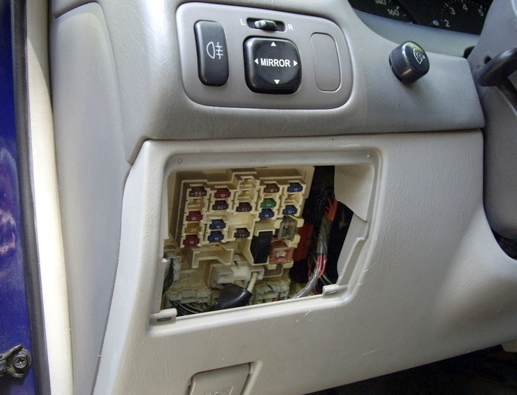
Example of legend from the cover
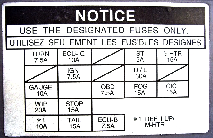
Diagram
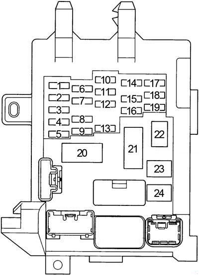
Assignment
| 1 | 7,5A TURN – Direction indicators, hazard warning lights |
| 2 | – |
| 3 | 10A GAUGE – Instrument cluster, reversing lamps, air conditioning, glass lifters, heated rear window, central locking |
| 4 | 20А WIP – Screen wiper and washer |
| 5 | 10A DEFI I / UP – Multiport fuel injection system / sequential multiport fuel injection system, M − HTR – Mirror control unit |
| 6 | 10A ECU-IG – Starting system, cooling fan, gear selector lock, ABS, cruise control |
| 7 | 7.5A IGN – Multiport fuel injection system / sequential multiport fuel injection system, charging system, airbags, seat belt pretensioners |
| 8 | 15A STOP – Brake light lamps, additional brake light, ABS, gear selector lock |
| 9 | 15A TAIL – Side light, instrument cluster, instrument panel light, license plate light, cigarette lighter , clock, audio system, heated rear window, automatic transmission control unit, multiport fuel injection system / sequential multiport fuel injection system, air conditioning, alarm |
| 10 | – |
| 11 | – |
| 12 | 7.5А OBD – Diagnostic connector |
| 13 | 5 / 7.5A Airbags, seat belt pretensioners, rear fog light |
| 14 | 5A ST – Starting system, multiport fuel injection system / sequential multiport fuel injection system |
| 15 | 30А D / L – Central locking |
| 16 | 15A FOG – Fog light |
| 17 | 15A S-HTR – Heated seats |
| 18 | – |
| 19 | 15A CIG – Audio system, clock, cigarette lighter , power mirrors, airbags, anti-theft system, pre-tensioners, gear selector lock |
| 20 | – |
| 21 | Fuse: "DOME" |
| 22 | 30 / 40А DEF – Heated rear window, fuse: "DEF I − UP / M − HTR" |
| 23 | 30A POWER – Glass lifters, sunroof |
| 24 | Jumper |
The fuse number 19 at 15A is responsible for the operation of the cigarette lighter.
Some relays are attached to the back of the unit.
Diagram

Designation
- A – Rear window defogger relay (DEF)
- B – Relay of dimensions (TAIL)
- C – Integrated relay
Relay box No. 1
Diagram

Assignment
| R1 | Direction indicators (hazard warning lights) |
| R2 | Fuel pump (C / OPN) |
| R3 | Glass lifters (P / W) |
Relay box No. 2
Diagram

Description
- 15A A / C – Air conditioner, cooling fan
- 40A HEATER – Air conditioning / heater, fuse: "A / C"
- R1 – Heater relay (HTR)
Electronics boxes engine compartment
Layout diagram

Designation
- Glow plug relay
- Fuse and relay box
- Relay box No. 1
- Headlight wiper relay
- Relay box No. 2
Fuse and relay box
Located on the left side of the engine compartment next to the pillar.
Photo – an example and a diagram from the block cover
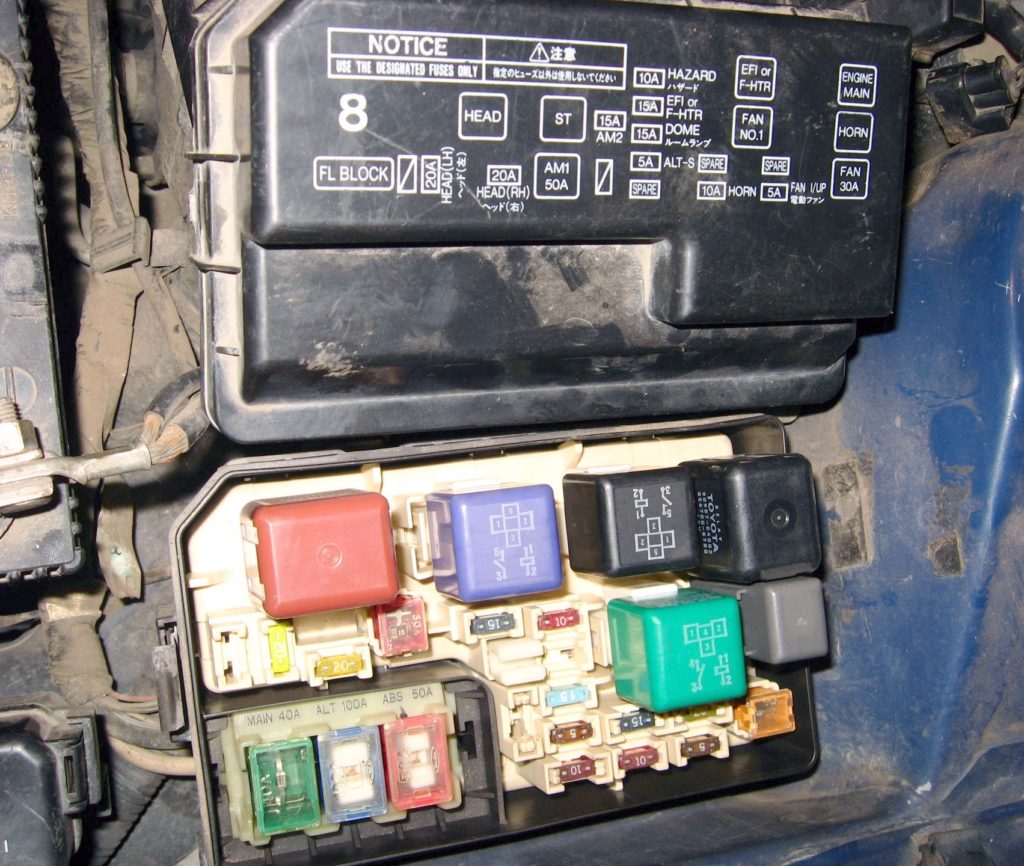
Diagram
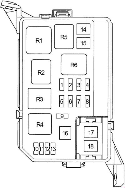
Protected components
| 1 | 5А ALT-S – Charging system |
| 2 | 10A HEAD (RH-UPR) – Right headlight (DRL – daytime running lights) |
| 3 | 15A EFI – 4A-FE, 5A-FE, 7A-FE, 4E-FE: Multiport fuel injection system / sequential multiport fuel injection system |
| 15A F-HTR – 2C-E: Multiport fuel injection system / sequential multiport fuel injection system | |
| 4 | 10А HORN – Sound signal, anti-theft system |
| 5 | 10А HAZARD – Hazard warning system, direction indicators |
| 6 | 15A AM2 – Starting system, fuses: "ST", "IGN" |
| 7 | – |
| 8 | 10A HEAD (LH-UPR) – Left headlight (DRL – daytime running lights) |
| 9 | 15А DOME – Audio system, interior lighting, personal lighting, luggage compartment lighting, clock, daytime running lights, anti-theft system |
| 10 | – |
| 11 | – |
| 12 | – |
| 13 | – |
| 14 | 50А AM1 – Fuses: "CIG", "TURN", "GAUGE", "ECU-IG", "WIP" |
| 15 | 30A FAN – Cooling fan |
| 30A RDI – Cooling fan | |
| 16 | 40A MAIN – Starting system, fuses: "HEAD (LH) or HEAD (LH-UPR)," HEAD (RH) or HEAD (RH-UPR), "HEAD LH-Lo" and "HEAD RH-LO" |
| 17 | 100А ALT – Fuses: "RDI", "CDS", "AM1", "POWER", "D / L", "TAIL", OBD, "FOG", "ECU-B", "STOP", "DEF" , "HTR" |
| 18 | 50A ABS – ABS |
Relay
| R1 | Engine control unit (ENGINE MAIN) |
| R2 | 4A-FE, 5A-FE, 7A-FE, 4E-FE: Engine control unit (EFI) 2C-E: Fuel heating (F-HTR) |
| R3 | Headlights (HEAD) |
| R4 | Starter (ST) |
| R5 | Sound signal |
| R6 | Cooling fan (FAN NO.1) |
Relay box No. 1
Diagram

Assignment
| 1 | 30A CDS – Cooling fan |
| 2 | 10A HEAD (LH-LWR) – with DRL: Left headlight (DRL – daytime running lights) |
| 3 | 15A HEAD (RH-LWR) – with DRL: Right headlight |
| 4 | 7,5А DRL – Daytime running lights |
| R1 | Dimmer |
| R2 | Cooling fan (AC FAN NO.2) |
| R3 | Cooling fan (AC FAN NO.2) |
| R4 | Air Conditioning Compressor Clutch (AC MG) |
Relay box No. 2
Photo – example of location

Diagram

Appointment
| R1 | ABS valve (ABS SOL) |
| R2 | ABS pump (ABS MTR) |
Do you know how to make this material better – we will be glad to receive your comments.
We use cookies on our website to give you the most relevant experience by remembering your preferences and repeat visits. By clicking "Accept", you consent to the use of ALL the cookies.
Posted by: gabrieldownum.blogspot.com
Source: https://fuseandrelay.com/toyota/corolla-110.html